27 : Hardware electric specification, Option.

sensor jack:
Analogue side:
we used special balanced DC coupling op amp, total Gain = 50,000 to 50,458.
Amplifier differential impedance is 10 T ohm,
Input Bias current is ±1.2 PA .. ±2 PA.
10 M ohm to 100 M ohm resistance input coupling.
variable high cut frequency filter amplifier Max 900 Hz -3bd.
Low cut 0.16 Hz at -3bd.
Common mode noise is up to 110 dB at 0..40 Hz.
Input Noise:
voltage noise
fB = 10 Hz to 10 KHz -> 0.6 µ Vrms .. 0.7 µVrms
fB = 0.1 Hz to 10 Hz -> 1.2 µ Vp-p .. 1.6 µVp-p
Current noise:
fB = 0.1 Hz to 10 Hz -> 12 fAp-p .. 15 fAp-p.
fo = 0.1 Hz to 20 KHz -> 0.6 fA/*Hz .. 0.8 fA/*Hz
Input Noise that depend on source impedance at 10 Hz:
10M ohm: 400 nV/*Hz, fB = 0.1 Hz .. 10 Hz -> 7.5µ Vp-p
1 M ohm: 120 nV/*Hz, fB = 0.1 Hz .. 10 Hz -> 2.4 µ Vp-p
100 K ohm: 50n nV/*Hz, fB = 0.1 Hz .. 10 Hz -> 1.2µ Vp-p
Analog side:
total Gain = 50,000 to 50,458. --> 25,000 (24,240 to 26,664)
Input Bias current is ±1.2 PA .. ±2 PA. --> 4 PA (TYP)
variable high cut frequency filter amplifier Max 900 Hz -3bd. ==> 10% - 100% to sampling frequency -3db
Common mode noise is up to 110 dB at 0..40 Hz. --> Common-Mode Rejection Ratio ? OPA2107 is 94db.
But, this time,
Important side is TL062's value. It's 86db.
This adjustment is very effective.
This adjustment is not in old IBVA.
I am searching a better OPA (for replace TL062). If it changes, I inform to you.
AD706 is 106db. But, AD706 is not good. (more 2.5mA per channnel is necessary for stability.)
Input Noise:
voltage noise
fB = 10 Hz to 10 KHz -> 0.6 ¬μ Vrms .. 0.7 ¬μVrms --> 0.85 ¬μ Vrms
fB = 0.1 Hz to 10 Hz -> 1.2 ¬μ Vp-p .. 1.6 ¬μVp-p --> 1.2 ¬μ Vrms
Current noise:
fB = 0.1 Hz to 10 Hz -> 12 fAp-p .. 15 fAp-p. --> 23 fAp-p
fo = 0.1 Hz to 20 KHz -> 0.6 fA/*Hz .. 0.8 fA/*Hz --> 1.2 fA/*Hz
Input Noise that depend on source impedance at 10 Hz:
10M ohm: 400 nV/*Hz, fB = 0.1 Hz .. 10 Hz -> 7.5¬μ Vp-p --> There is not graph in pdf. 1 M ohm: 120 nV/*Hz, fB = 0.1 Hz .. 10 Hz -> 2.4 ¬μ Vp-p --> There is not graph in pdf.
100 K ohm: 50n nV/*Hz, fB = 0.1 Hz .. 10 Hz -> 1.2¬μ Vp-p --> There is not graph in pdf.
variable high cut frequency filter amplifier Max 900 Hz -3bd. --
There is another hi-cut filter.
Amp's cut-off is about 1.5KHz (-3db), even in the case that there is not a variable filter.
Yes. 16V to 6V (5.6 is ok)
Digital side:
10 bit AD convertor 120 to 1960 sample par second.
minimum input 0 micro V p-p generate number 0.
max. input 200 micro V p-p generate number 1024.
minimum digital resolution is 200 micro V p-p / 1024 = 0.1953125 micro V p-p generate number 1.
Radio frequency: Bluetooth Interface class 2
2400 - 2483.5 MHz for USA/Europe/Japan
2446.5 to 2483.5 MHz France
Electrode side:
we can get good signal even if skin and electrode impedance changed between 0 to 100 K ohm then 0.4 micro V p-p out put noise. this mean we can use different electrode easily.
Power:
one 9V battery operate about 1 to 2 hours.
16 V to 6 V is works.
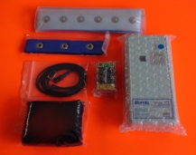
Order parts:
electrodes option sale as separately.
masahiro kahata
Psychic Lab, Inc.
The Transmitter Amplifier