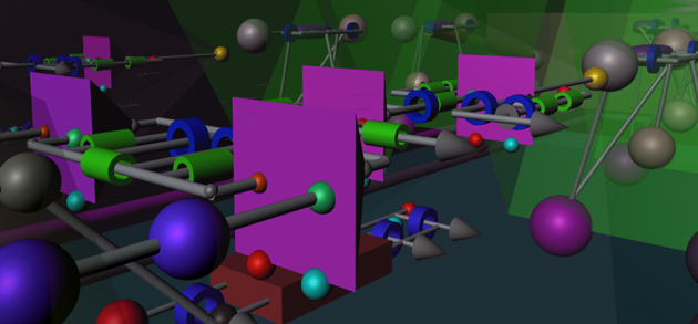
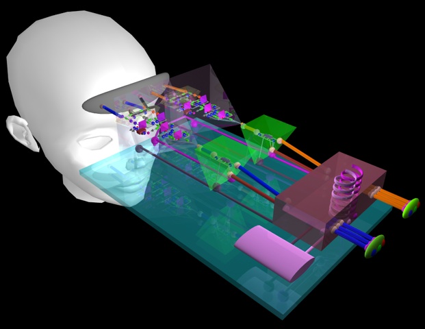
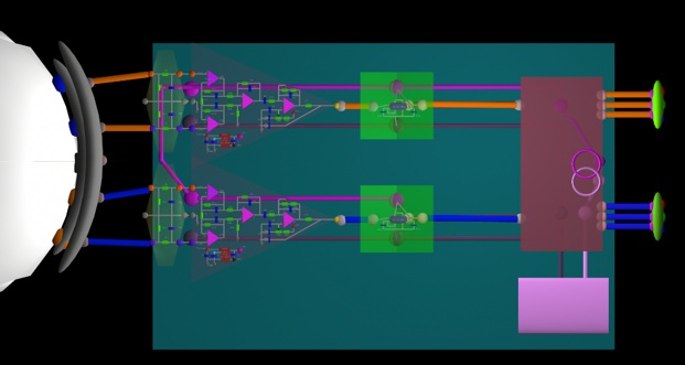
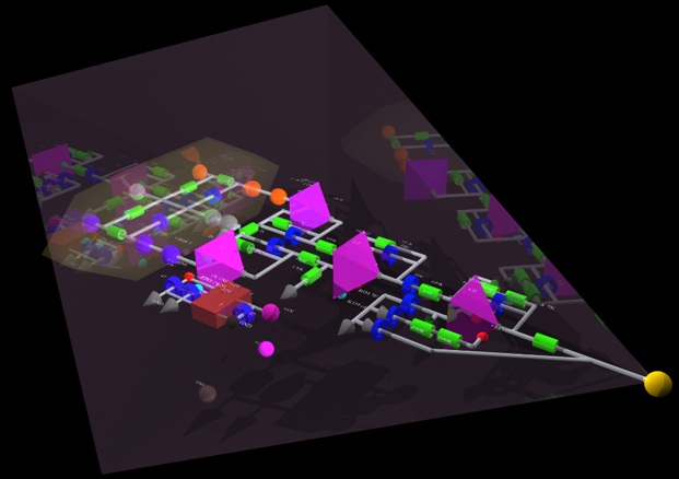
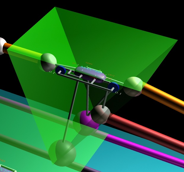
2: open brain wave interface hardware circuit diagram


UK news paper daily telegraph 1997.
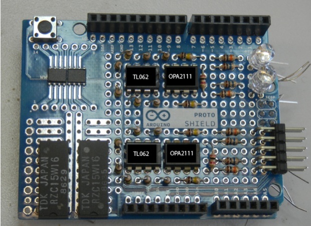
this diagram is based on prototype 1, 2 and 3 and put together with Arduino BT. updated Sep 18, 2012.
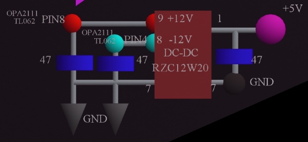
AMP parts diagram
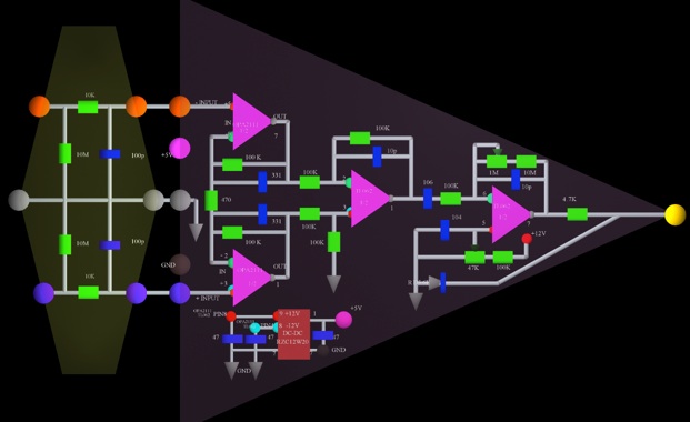
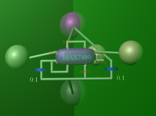
high cut filter
Parts list :
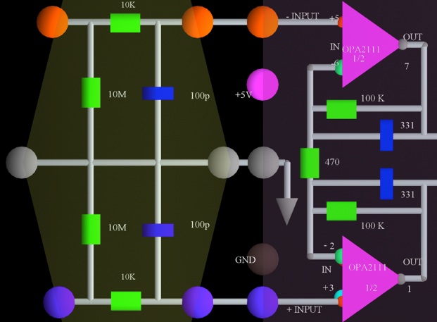
head amp : OPA2111 X 2
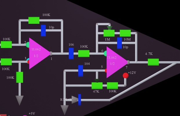
offset amp : TL062 X 2
filter IC : MAX 7480 X 2
R : 10 M ohm X 6
R : 100 K ohm X 14
R : 10 K ohm X 4
R : 4.7 K ohm X 2
R : 470 ohm X 2
C : 47 µF 16V X 6 ( this parts has polarity. + side goes to + power, - side goes to - power )
C : 106 X 2 ( 10 µF = 10,000,000 pF : low cut 0.16 Hz, use 1 µF is low cut 1.6 Hz)
C : 104 X 6 ( 0.1 µF = 100,000 pF)
C : 331 X 4 ( 330 pF)
C : 100 pF X 4
C : 10 pF X 4
Zener Diode : RD5.6E X 2
Trimer : 1 M ohm X 2
Trimer : 47 K ohm X 2
DC-DC : RZC12W20 X 2 ( can use other company’s DC-DC. +/- 12 V, 50 mA )
Arduino BT : X 1
Arduino Proto Shield : X 1
RGB LED : X 2
also you need to connect battery ( 2.0 V .. 5.2 V ) to Arduino BT.
( when 2.0 V : 520 mA, 2.7 V : 350 mA, 3.9 V : 220 mA, 4.5 V : 200 mA, 5 V : 180 mA )
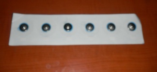
need to make or buy cable and electrode head pad and electrode.
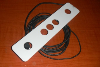
medical electrodes
this unit works with same Arduino code as prototype 1 unit.
also can use
Quartz Composer IBVA plugin XCODE for Mac is Open source. included sample QC file to show Raw data.
Brainbay IBVA plugin for OpenEEG project PC is Open source.
http://www.psychiclab.net/IBVA/BrainBay.html
also can use IBVA V5 application for Mac.
in case you like you can buy it.
http://www.psychiclab.net/IBVA/IBVAnew2.html
construction Photo and test procedure :
under construction.
waiting to get some parts.
this diagram is basically same as i used over 30 years. so it should work.
in case you like you can start make same way. and/or you can wait until i finish to make this. maybe need some changes.
so many times i made this amp parts different way, but head amp is same amp electric circuit design.
need to set two trimer, total gain and offset for AD input of Arduino.
need to set 200 micro V p-p input makes 5 V p-p to Arduino analog input. Total gain is 25,000.
also 2.5 V offset to Arduino analog input. output need to set 0 to 5 V.
audio amplifier and brain wave amplifier difference is source impedance and frequency response.
usually audio amplifier design to use low impedance source: like 4 ohm, 8 ohm, 200 ohm, 600 ohm, 1 K ohm, 10 K ohm, 100 K ohm, this mean easy to make low noise amplifier but need wide frequency range. low frequency is 5 Hz, 10 Hz, 20 Hz high frequency is 20 K Hz, 40 KHz, 80 KHz, 200 KHz.
brain wave amplifier need to design for high impedance source and low voltage and current noise, low DC drift, but less frequency range like low frequency is 0.16 Hz, 0.5 Hz, 1 Hz and high frequency is 30 Hz, 100 Hz, 300 Hz, 1000 Hz. also need to have 100 to 1000 times more gain than audio amplifier.
how to test:
Connect 100 K ohm impedance source oscillator is nice for noise test. put 1 to 10 micro V p-p, 1 .. 40 Hz sin wave.
amplifier noise is depend on skin and electrode impedance.
usually low impedance makes low noise. high impedance makes more noise.
not just only amplifier, resistance also has noise. this noise is depend on temperature. low temperature makes low noise, high temperature makes more noise. this amplifier OPA2111 noise is very similar as resistance noise. only way to reduce noise is make low temperature : this is current open technology limitation. we can not make low noise than resistance noise.
depend on skin and electrode conductance situation this noise will be change.
my head amp design try to eliminate this skin and electrode conductance situation depend on person and other issuer. Usually 10 K ohm to 1 M ohm is skin and electrode conductance. many years ago EEG technician's one of knowledge is how to put nice way electrode to skin. mean set low impedance between electrode and skin. because that time amplifier quality was not good when input impedance is high.
in generally say low impedance person is relaxed. high impedance person is more stress.
This unit can see less than 1 micro V p-p brain wave. it is professional quality EEG system.
digitally control filter works very nice. can set cut and/or no cut 50 Hz to 60 Hz AC power noise which come from any where in the room. 50 Hz and 60 Hz is depend on country, only Japan has two AC power frequency.
http://www.psychiclab.net/IBVA/50Hz60Hz.html
Can set Aurduino program to see this AC frequency also.
in case you like to see more high frequency than 50 Hz to 60 Hz AC power noise then need to careful for setup all system condition. it is not easy this setup for beginner.
Prototype 1 Aurduino code set this frequency to 40 Hz, so no problem for 50 Hz to 60 Hz AC power noise. however too many noise will still get AC noise.
doing experience outside is so nice to eliminate this AC noise.
‘
masahiro kahata
psychiclab.net


Index prototype prototype 1 prototype 2 prototype 3 code
2: open brain wave interface hardware circuit diagram.